3 Pin Ignition Coil Wiring Diagram / Ps Garage Motorsport Coil On Plug Wiring For Mitsubishi Engine 4g9x 4g6x - Testing the ignition coil and the igniter (ignition control module) is not hard.
3 Pin Ignition Coil Wiring Diagram / Ps Garage Motorsport Coil On Plug Wiring For Mitsubishi Engine 4g9x 4g6x - Testing the ignition coil and the igniter (ignition control module) is not hard.. Looking for help with wires pulled out from ignition coil plug on cylinder 2. Old coil wiring diagram 12 volt ignition coil wiring diagram pertaining to ignition coil condenser wiring diagram, image size 640 x honestly, we have been remarked that ignition coil condenser wiring diagram is being just about the most popular field at this time. Following table shows wire colors related to electrical circuits. On a factory hei, the primary coil leads will either be white and red, or yellow and red. Easy to read wiring diagrams for strat style guitars with 3 single coil pickups.
Diagram 2 in this circuit, a resistor is connected in parallel with the capacitor, and as the volume is turned lower, the higher frequencies are not as dominant. Anyone know why the ignition coil (on plug) needs to have 3 pins connector? Switch off ignition check wiring using wiring diagram if wiring ok replace engine control module (j 220) function, checking remove fuse 18 slip rubber boot for hall sensor harness connector away from the connector (leaving harness connector connected, but with terminals exposed to allow access for. Connect the red cable from. 4pin dc cdi wiring diagram of ignition system.
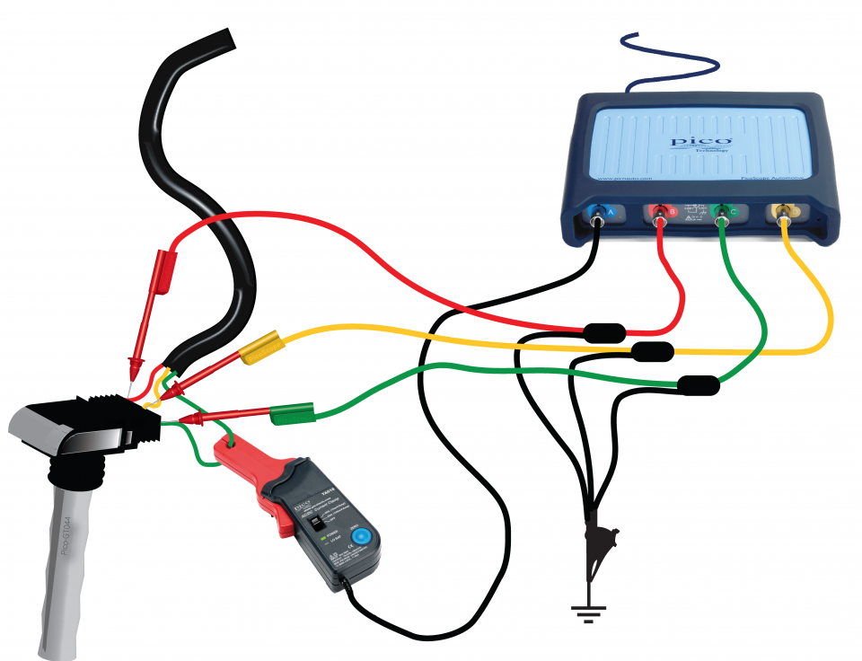
Coil On Plug Primary Voltage And Current 3 Wire from www.picoauto.com In this video explain ko lang po kung paano yung wiring diagram ng ignition system nothing else ✌ thanks for wathing. Looking for help with wires pulled out from ignition coil plug on cylinder 2. That shows what color wire connects to which coil? (3.4 n·m), coat with quicksilver. The following overviews each coil pin: I am trying to figure out what wires are what on my 95 integras ignition switch. Referring to the above capacitor discharge ignition circuit diagram, we see a simple configuration consisting of a few diodes, resistors. Taking apart a 2001 vortec 5.3 harness.
The coil is probably the easiest thing to check and therefore the first thing to check when embarking be sure to unhook the coil from the equipment wiring harness as well as the engine's wiring harness.
The following overviews each coil pin: Vw golf 3 1.6 abu ignition coil check, 3 pin coil with icm (ignition coil module). Item model manufacturer primary coil resistance secondary coil resistance insulation resistance between primary ignition coil and ignitor assembly. Coil induction & wiring diagrams. Ignition system ignition coil kohler engine parts schematic drawing electrical diagram electrical wiring vw parts diagram chart. At the dizzy and one wire has power goin through and my coil(external)also has power running to one wire but dosnt fire at coil when u turn it over.neither does. Rocker switch wiring diagram wire rod coil copper wire coil electrical coil wire wire coil winding machine flat wire amazon hot sale 1f3u12029aa auto engine spare parts ignition coil transformer tester pack wiring diagram for ford. You don't have that anymore, so you need an additional wire to. In this video explain ko lang po kung paano yung wiring diagram ng ignition system nothing else ✌ thanks for wathing. Brown brown blue pin 18. Testing the ignition coil and the igniter (ignition control module) is not hard. Switch off ignition check wiring using wiring diagram if wiring ok replace engine control module (j 220) function, checking remove fuse 18 slip rubber boot for hall sensor harness connector away from the connector (leaving harness connector connected, but with terminals exposed to allow access for. Ignition coil | testing ignition coils ✓ ignition coil failure:
Ignition system ignition coil kohler engine parts schematic drawing electrical diagram electrical wiring vw parts diagram chart. At the dizzy and one wire has power goin through and my coil(external)also has power running to one wire but dosnt fire at coil when u turn it over.neither does. Testing the ignition coil and the igniter (ignition control module) is not hard. Typical standard fender stratocaster guitar wiring with master volume plus 1 neck tone control and one middle pickup tone. In this video explain ko lang po kung paano yung wiring diagram ng ignition system nothing else ✌ thanks for wathing.
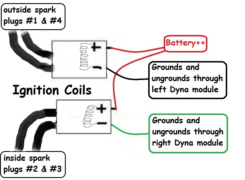
Diagram Softail Dyna Coil Wiring Diagram Full Version Hd Quality Wiring Diagram Studiolightingdiagrams Potrosuaemfc Mx from kzrider.com (3.4 n·m), coat with quicksilver. Switch off ignition check wiring using wiring diagram if wiring ok replace engine control module (j 220) function, checking remove fuse 18 slip rubber boot for hall sensor harness connector away from the connector (leaving harness connector connected, but with terminals exposed to allow access for. Schematics aren't likely available either. Connect the red cable from. How to trigger internal igniter ignition coils using a specific square waveform trigger signal. Following table shows wire colors related to electrical circuits. There are three different treble bleed circuits and many different recommended values for the components. Referring to the above capacitor discharge ignition circuit diagram, we see a simple configuration consisting of a few diodes, resistors.
Does anyone have a wiring diagram?
Taking apart a 2001 vortec 5.3 harness. Typical standard fender stratocaster guitar wiring with master volume plus 1 neck tone control and one middle pickup tone. Does anyone have a wiring diagram? Connect the red cable from. On a factory hei, the primary coil leads will either be white and red, or yellow and red. Pics if possible will be appreciated. The following overviews each coil pin: Looking for help with wires pulled out from ignition coil plug on cylinder 2. Related searches for ignition coil wiring diagram: Finding out how to read wiring diagrams is similar to learning a new language. Ignition system ignition coil kohler engine parts schematic drawing electrical diagram electrical wiring vw parts diagram chart. The ignition coil, which is very popular and we all have seen them in our vehicles is especially designed for the above stepping up of the input source voltage. You don't have that anymore, so you need an additional wire to.
Item model manufacturer primary coil resistance secondary coil resistance insulation resistance between primary ignition coil and ignitor assembly. Related searches for ignition coil wiring diagram: Anyone know why the ignition coil (on plug) needs to have 3 pins connector? Vw golf 3 1.6 abu ignition coil check, 3 pin coil with icm (ignition coil module). There are three different treble bleed circuits and many different recommended values for the components.
Accuspark Wiring Diagrams from www.ccee.nl I am trying to figure out what wires are what on my 95 integras ignition switch. Coil induction & wiring diagrams. Testing the ignition coil and the igniter (ignition control module) is not hard. Red wire goes to pin #1, light blue with black strip wire goes to pin #2, light blue with red strip wire goes to pin #3, and white with black. Vw golf 3 1.6 abu ignition coil check, 3 pin coil with icm (ignition coil module). Following table shows wire colors related to electrical circuits. Looking for help with wires pulled out from ignition coil plug on cylinder 2. Ignition coil | testing ignition coils ✓ ignition coil failure:
I am trying to figure out what wires are what on my 95 integras ignition switch.
Pics if possible will be appreciated. Related searches for ignition coil wiring diagram: The ignition coil, which is very popular and we all have seen them in our vehicles is especially designed for the above stepping up of the input source voltage. Diagram 2 in this circuit, a resistor is connected in parallel with the capacitor, and as the volume is turned lower, the higher frequencies are not as dominant. The colors of the leads determine the direction the coil is wound, which determines its polarity. Red wire goes to pin #1, light blue with black strip wire goes to pin #2, light blue with red strip wire goes to pin #3, and white with black. Anyone know why the ignition coil (on plug) needs to have 3 pins connector? Looking for help with wires pulled out from ignition coil plug on cylinder 2. Connect the red cable from. Coil induction & wiring diagrams. Brown brown blue pin 18. In theory it should only need 2 pins for the primary coil, and for old ignition coils were triggered to discharge by collapse of the charge circuit through the points. I am trying to figure out what wires are what on my 95 integras ignition switch.